Type 3380-1100
Proportional Servo Electric Actuator
Type 3380-1100
Application
Remote control for:
Features
General
3380 actuators are designed and manufactured for long trouble free service with corrosion resistant materials. Long operational life can be expected due to generously proportioned design.
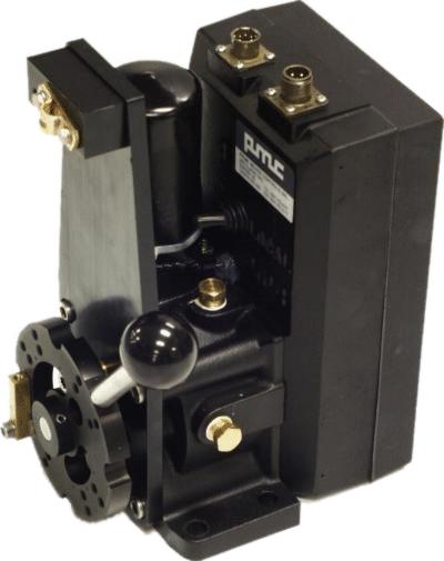
The 3380 actuator contains a permanent magnet DC gear motor that drives a push-pull cable or lever through an adjustable friction clutch. It also contains a servo amplifier printed circuit board and a feedback potentiometer.
The 3380-1100 electric servo actuator converts an electrical command signal into mechanical motion. It positions an output lever or push pull cable in a position proportional to the command signal.
The actuator includes a manual override switch marked REMOTE and LOCAL. Select LOCAL to disable remote control of the actuator and allow the operator to move the output lever manually.
In case of electrical failure, the actuator is set to the local control mode and the optional external backup motor control circuit is automatically activated.
Two Bendix, Mil. Spec. type connectors are used to connect the actuator to the control system. One is the 6 pin main control connector and the other is the 3 pin backup control connector.
Input Protection
Several input protection circuits are employed to
provide protection against: reverse connection of
24 VDC, connection of 120 VAC, and connection of voltages in excess 35
VDC.
Limit Switches
Internal travel limit switches can be provided if required. Once a limit switch activates, no further motion is allowed in that direction. The motor is permitted only to drive away from the limit switch.
Low Power Mode
If the actuator is prevented from following up, the internal slip clutch will prevent the motor from stalling. If this condition persists for a predetermined time, the actuator will go into low power mode. In this mode the motor voltage is reduced and the motor stops. When the actuator is freed it will move slowly into position. A non follow up alarm will occur when in low power mode. The actuator can remain in low power mode indefinitely without being damaged.
Manual Override
In manual override mode, the actuator motor can be driven directly from a backup power source. The actuator can also be moved with the manual handle. Manual override mode is selected by switching the manual override switch on the actuator to the LOCAL position, or by connecting the manual override line to zero volts. A primary power failure to the actuator will also allow backup control. During backup control the power to the motor is switched by an internal relay and bypasses all internal electronics.
Backup control disables the non follow up alarm. It is recommended that the backup power be controlled by a spring centered jog switch. This will prevent the motor from accidentally being driven when the power is switched. The backup power source is supplied to the actuator through a separate backup connector.
Typical Installations
| Home | PRIME MOVER
CONTROLS INC. 3600 GILMORE WAY, BURNABY B.C. CANADA V5G 4R8 TEL (604) 433-4644 FAX (604) 433-5570 email:info@pmc-controls.com |