|
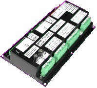
Series 8503-2000
Digital Servo Controller
Electric Shaft / Propulsion Telegraph
Electric Shaft
The electric shaft control system is an electrical alternative to mechanical shafting for interconnecting remote control levers on a ship. Moving the control lever at one station causes all other levers in the system to follow. This provides continuous display at all stations of the position of the lever at the controlling station. Because all control levers are continually aligned, control transfer between stations is smooth and "bumpless".
Telegraph
The propulsion telegraph provides a means of communication between the bridge and engine room. This communication is in the form of orders placed and acknowledged by moving the command / reply lever to align with the acknowledge / command pointer.
Features
- Single or twin screw
- Up to nine bridge units and six engine room units
- Telegraph compatible with Type 8202 push button telegraphs
- Optional independent command position outputs (4 mA to 20 mA or 2 kHz to 12
kHz)
- Optional gateway for connecting to data logger, printer or PLC
- Reliable communication and transceiver technology for the marine environment
- Dual 24 VDC inputs use ship's power supplies
- Self diagnostics with status indication
- Relay output for unit fault
- Marine approvals
Specifications
Supply:
- Dual 24 VDC inputs
- Nominal 24 VDC
, range 18 to 35 VDC
- Reverse and over voltage protection to 120
VAC
- 325 mA nominal, 1.5 A max
- Input power fuse: 2 A slow blow, type MDA-2
- Command signal power, internal 120 mA self resetting PolySwitch (fuse)
Inputs / Outputs:
- Bell relays: NO contact, 5 A @ 250
VAC / 30
VDC
- Fault relay: NO contact, 1 A @ 30
VDC
- General inputs: optically
isolated nominal 24 VDC
- General output: open collector, 100 mA max
- Optional independent command position outputs (4 mA to 20 mA / 2 kHz to 12
- kHz)
- Lever / Pointer motor drivers: 24
VDC
, 1.3 A current limiting
Communication:
- Cable: single 16 AWG twisted pair
- Bus Topology, total wire length 2700 m
- Free Topology, total wire length 500 m
- Optional repeater to extend total wire length
- Tx & Rx activity LEDs
Environmental:
- Storage temperature -40 °C to +85 °C
- Vibration: Frequency range 2 Hz to100 Hz
- Peak to peak amplitude 2 mm below 13.2 Hz
- Acceleration amplitude 0.7 g
above 13.2 Hz
Physical:
- IP40
- Dimensions:
- 267 mm L × 140 mm W × 60 mm H
(10.5" L × 5.5" W × 2.35" H)
- Weight, typical 0.8 kg (1.8 lbs)
- Removable terminal blocks for 14 to 20 AWG wire
Diagnostics:
- Fault relay: NO contact, 1 A @ 30
VDC
- Watchdog LED
- Diagnostic LED flashes error codes
- Tx & Rx activity LEDs
System Accessories Available from PMC:
- Control heads
- Wrong direction sensors
- Bells, horns and lights
- Gateway connection to data logger, printer or PLC
- Project specific connection diagrams drawn with AutoCAD
- Factory system integration and assembly
- Factory system test

| Home |
PRIME MOVER
CONTROLS INC.
3600 GILMORE WAY, BURNABY B.C.
CANADA V5G 4R8
TEL (604) 433-4644 FAX (604)
433-5570 email:info@pmc-controls.com |
|
|