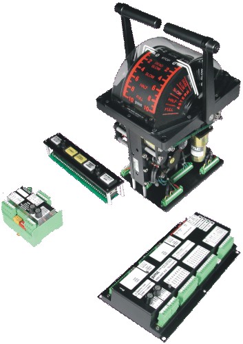
| Propulsion Order
Telegraph System Series 8503-2000 Digital Servo
Controllers are used in conjunction with Type 5401-1100 telegraph heads to
form a traditional lever style telegraph system.
The propulsion telegraph system provides a means of
bi-directional communication between the bridge and the engine room. This
communication is in the form of orders placed and acknowledged by moving the
command levers.
The system uses dual 24 VDC
inputs from ship’s power supplies and serial communication with error
detection to ensure trouble free operation.
Relay outputs are provided for an order bell and a wrong
direction alarm.
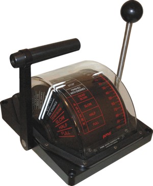
Telegraph Orders
An order is placed by moving the lever at the bridge
station in command to the desired order. This causes the reply pointers at
all engine room stations to move to the same position as the command lever
on the bridge.
Whenever the reply pointer and the lever at an in command
telegraph are not aligned, the external bells sound, at both in command
locations, to indicate a new order.
Once the in command engine room lever is moved to align
with it’s own reply pointer, all bridge reply pointers will follow up and
align with the engine room lever. All audible devices will silence. The
engine room can transmit orders to the bridge in the same manner.
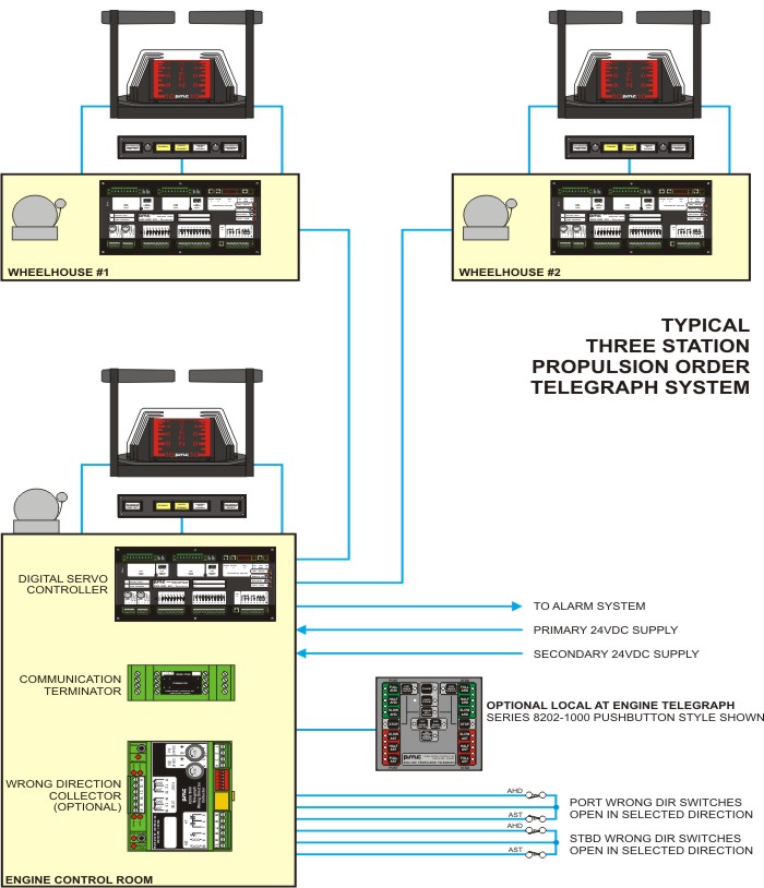
Multiple Station System
The propulsion telegraph system can operate from multiple
bridge and engine room stations.
When a ship has one bridge station and one engine room
station, both the bridge and engine room station are always in command.
When a ship has more than one station in the bridge and/or
more than one station in the engine room command transfer is required.
Generally a telegraph command transfer button is used to transfer command.
The control transfer logic can be performed by the Digital
Servo Controller or via external logic (PLC, relays, or control transfer
boards). |
Auxiliary Orders
Auxiliary telegraph orders such as Standby, Cancel Standby
and Finished With Engines can be integrated into the lever telegraph.
Auxiliary telegraph orders can also be external pushbuttons.
Wrong Direction
An optional wrong direction alarm, with adjustable time
delay, is activated when the direction of propulsion is not the same as the
acknowledged telegraph order. This feature advises the engineer and captain
when the machinery direction does not match the acknowledged order or if the
machinery drifts to a direction other than the established setting. Ahead,
Stop and Astern are considered distinct directions and are monitored by the
wrong direction circuitry.
When auxiliary telegraph orders are present on the lever
telegraph scale, wrong direction alarms are disabled for any acknowledged
auxiliary order. When external push buttons are used for the auxiliary
telegraph orders, wrong direction alarms are disabled for acknowledged
Finished With Engines and Bridge Control orders, but enabled for Standby and
Cancel Standby orders.
Pushbutton Telegraph Stations
Series 8202-1000 Push Button Telegraphs can be connected
to a Series 8503-2000 Digital Servo Controller. The lever telegraph and the
push button telegraph communicate on the same network.
Command Position
Optional command signal transmitters can be installed at
the factory. These transmitters work independently of the telegraph
circuitry in the Digital Servo Controller. Each transmitter has it's own
power supply with a self resetting internal fuse. Even with a complete
failure of other circuitry on the Digital Servo Controller the transmitter
will continue to function properly.
Diagnostics
Troubleshooting guidance is provided by a Watchdog LED and
a Fault Code LED. Under normal operating conditions the Watchdog LED will
flash.
The Fault Code LED flashes two digit codes which
correspond to particular fault conditions. A fault relay opens on a general
system fault. |


